Emergency light
For the animated playground of Holsbeek
Finished on November 5, 2015
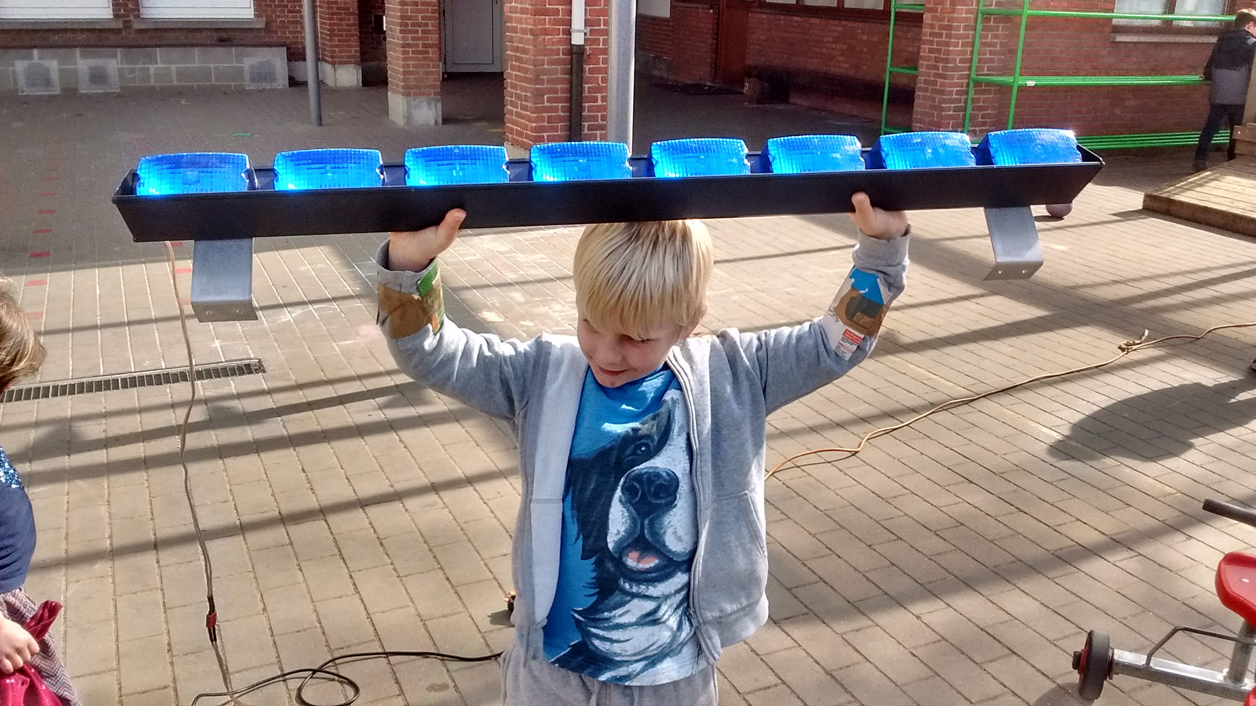
"I found this emergency light, can you make something out of it?" is what my friend Tom asked while handing me what seemed like an ill-gotten piece of law enforcement vehicle. He wanted me to make it into a child-friendly toy for our animated playground and I just couldn't resist playing with it.
Tom was the coordinator of our animated playground, this means he was a municipal official. He always gets along well with everybody and this included the local police department. They recently switched to LED lights and had no use for the old light array. Knowing what Tom did, they asked him if the animated playground had a use for it.
The lights did not come with a controller because the cops still needed it. This is why Tom asked me to put some buttons on it and make it flash. The 8 halogen lamps draw almost 3A of current each at their rated 12V. The controller board inside the array had connectors for a serial control signal. But without any reference, it seemed too hard to figure out. This is why I decided to build my own controller board. It would have to be small to fit in the case, it would need large traces to handle the current and since someday someone might want to try and reprogram it, I wanted this to be easy as well.
Making a PCB
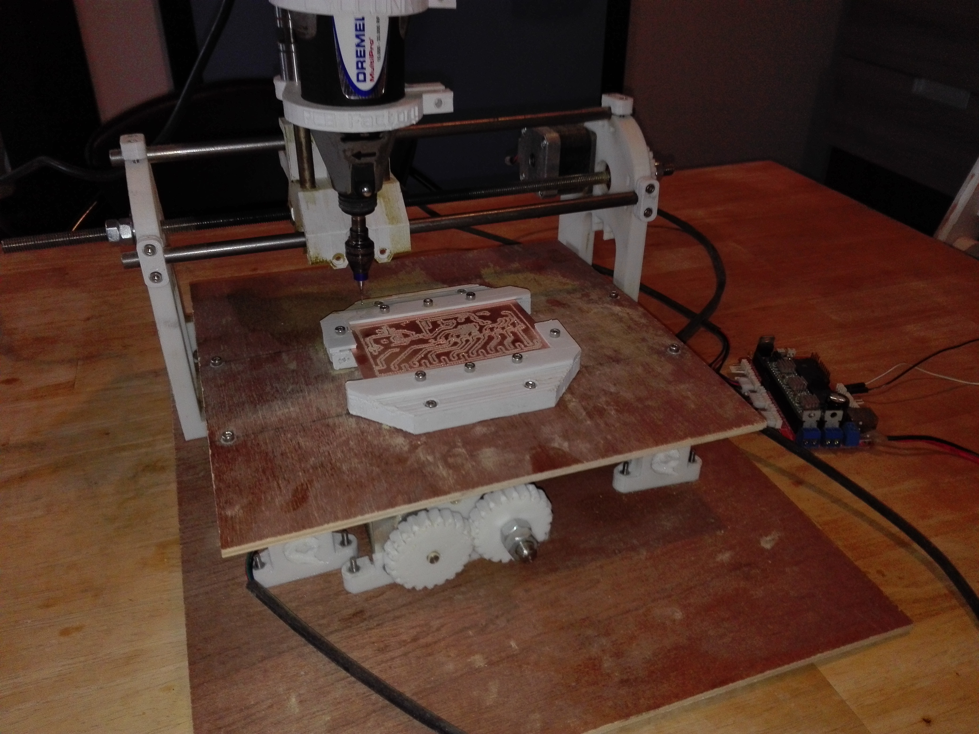
The Cyclone PCB factory.
Working with perforated board was not really an option because of the size of the case. Ordering a single PCB (I had no use for others) seemed a bit silly too. Taking into account I had no experience with these kinds of currents, I had no idea whether my first design would even work. So I decided to make a PCB myself. I had tried the toner transfer method before but never had any success. So this time I decided to go the mechanical way.
I took the plans for the cyclone PCB factor (link) and started 3d-printing on the RepRap I made a while back. The cyclone PCB factory is a 3d-printed CNC machine specifically made for milling out PCBs. Because of some problems with my RepRap and me skimping out on decent wood for the base, the PCB factory came out a lot less accurate than expected. Luckily I needed very wide traces for this project, so this wasn't really a problem. After a while, I was milling out one PCBs after the other.
Fitting it all together
A video of when I was testing the chaser patterns. The quality is rather bad because this was meant as a proof of concept for Tom.
The rest of the project went without too many hiccups. Some big MOSFETs and an ATmega168 to be compatible with the Arduino platform was all I really needed. While measuring the circuit I did short out part of the PCB burning a trace. This comes to no surprise with a 360W power supply. I was pretty glad I could just mill out another board and didn't have to wait for a PCB to arrive. Even though the damages were limited, I am a lot more careful when working with high currents ever since. After drilling the holes for the push buttons and wiring everything up the case slid back together like a charm. All that rested was to 3d print a cover to protect the power supply and the project was finished.
The light has 9 buttons. 8 of them are used to switch the lights on or off individually. When the 9th button is pressed the light goes into party mode. Now each of the 8 buttons activates a chaser pattern. The kids of the animated playground love playing with the buttons and it has been used for every party we had since.